Teams:
KCIRI team and Department of Aeronautical Engineering
Industry:
Defence Research & Development Laboratory – DRDL
Abstract:
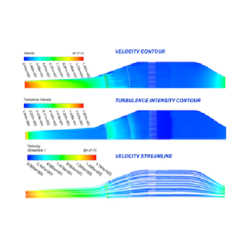
Tri-Sonic Wind tunnel is capable of producing three speed regimes in the test section namely Subsonic, Transonic and Supersonic. DRDL is working on establishing Tri-Sonic wind tunnel to test aerospace vehicles at the mach number range from 0.4 to 4.0 with test duration of 30-40 sec. The tunnel will be intermittent blow down type with air stored at high pressure expanded through a nozzle to provide the required test Mach number. The tunnel will consist of storage vessel, Pressure regulating valve (PRV), Settling Chamber, Nozzle, Test Section and variable area Supersonic Diffuser. The air coming downstream of PRV will be chocked and highly turbulent. The non-uniformity and unsteadiness of the flow in the test section will adversely influence quality of the measured data and can cause transition of boundary layer location. It can also lead to high uncertainty in the measured data on the model. It is hence necessary to damp out these pressure fluctuations and reduce the turbulence of the flow before it enters the test section. To address this, a settling chamber upstream of the nozzle is used to convert the hi-turbulent flow to a low constant-pressure flow with vastly reduced turbulence.
The cross sectional area of the wide angle diffuser increases rapidly to achieve the required area-ratio over a minimum length. This is bound to cause separation, which can be avoided by adding perforated plates at well-chosen locations. The straight cylindrical portion has a honeycomb flow modifier followed by turbulence reducing wire mesh screens. This is then followed by converging portion.
In the straight portion, a combination of honey comb and a set of wire mesh screens are provided to reduce the turbulence level. The contraction cone will be designed for smooth transition from upstream circular cross-section into a rectangular cross-section at exit.
Application:
Wind Tunnel Testing of aerodynamic models in tri-sonic regime